Table of Contents
Shaper Machine
A shaper machine is a reciprocating type of machine tool that is used for producing flat, horizontal, vertical, or angular surfaces with the help of a single-point cutting tool.
It works on a quick-return mechanism where the ram moves the tool forward to cut and returns it idle.
It uses linear relative motion between the workpiece and cutting tool to machine a linear toolpath.
- It can create any surface composed of straight line elements.
- It carries a single point cutting tool in the ram and workpiece is fixed in the table.
The shaper machine is commonly used in the metalworking industry and machine shops for precision machining operations.
- This machine was developed in the year 1836 by James Nasmyth and Englishman.
Definition of Shaper Machine
A shaper machine is a reciprocating machine tool that uses a single-point cutting tool to produce flat, angular, grooved, or slotted surfaces.
Mechanism of Shaper Machine
- In a standard shaper, the metal is removed in the forward cutting stroke as well as the return stroke goes idle and no metal is removed during this period.
- To reduce the total machining time this is necessary to reduce the time taken by the return stroke.
- Thus, it should be so designed that it can allow the ram holding the tool to move at a comparatively slower speed during the forward cutting stroke.
- The cutting speed depending upon the types of material and machining condition, whereas during the return stroke it can allow the ram to move at a faster rate to reduce the idle return time.
- This mechanism is known as quick return mechanism.
- In quick return mechanism we use crank slotter mechanism.
Working & Principal of Shaper Machine
Working
- In a shaper machine, the workpiece is typically held stationary on a table, while the cutting tool is mounted on a ram that moves back and forth.
- Shaper is primarily used to produce flat smooth surfaces with special attachments.
- They can also produce internal and external keyways, gear racks, spiral grooves, T- slots, etc.
Principle
- It states that the cutting tool travels back and forth over the work for machining.
Types of Shaper Machine
- There are 9 types of shaper machine according to their features of design or the purpose:-
1. Crank type shaper machine
2. Push type shaper machine
3. Draw type shaper machine
4. Geared types shaper machine
5. Horizontal type shaper machine
6. Vertical type shaper machine
7. Standard type shaper machine
8. Universal type shaper machine
9. Travelling head type shaper machine
1. Crank type shaper machine
- Crank shaper is the most common type of shaper in which a single point cutting tool is used to provide a reciprocating motion i.e. equal to the length of the stroke desired.
- The crank shaper employs a crank mechanism to change circular motion of a large gear that is called ” bull gear “.
- The bull gear gets power either from an individual motor or from an over head line shaft in the event that it is a belt driven shaper.
2. Push type shaper machine
- Push shaper is the most general type of shaper that is utilized in common practice.
- The metal is taken out when the ram moves away from the column, i.e. pushes the work.
3. Draw type shaper machine
- In a draw shaper, the metal is taken out when the ram moves towards the common of the machine, i.e. draws the work towards the machine.
- The tool is fixed in a reversed direction to that of a standard shaper.
- The ram is generally supported by an overhead arm which guarantees inflexibility and eliminates deflection of the tool.
- The cutting pressing factor acts towards the column which relieves the cross rail and different bearings from excessive loading and allows to take deep cuts.
- Vibration in these machines is practically eliminated.
4. Geared types shaper machine
- The reciprocating motion of the ram in some kind of shaper is affected through a rack and pinion.
- The teeth of the rack that is cut directly below the ram mesh with a spur gear.
- The pinion fitting with the rack is driven by a gear train.
- The speed and the direction in which the machine will traverse depends on the number of gears in the gear train.
- This kinds of shaper isn’t broadly utilized.
5. Horizontal type shaper machine
- In this kinds of shaper, the ram holding the tool which reciprocates in a horizontal axis.
- Horizontal shaper are mainly used to produce flat surfaces.
6. Vertical type shaper machine
- In this types of shaper, the ram holding the tool reciprocates in a vertical axis.
- In some of of the vertical machines arrangement is made to permit change of the ram to an angle of about 10 degrees from the vertical position.
- This kinds of a shaper may be crank driven, rack driven, screw driven or hydraulic power driven.
- The work table of a vertical kinds of a shaper can be given cross, longitudinal, and rotary movement.
- The tool is entirely different from that utilized on a horizontal shaper.
- They are extremely advantageous for machining internal surfaces, keyways, slots or grooves.
- The large internal and external gears may also be machined by the rotary table arrangement of indexing.
7. Standard type shaper machine
- The shaper is named as standard or plain when there table has only two movements, vertical and horizontal, to give the feed.
- The table may or may not be supported at the outside end.
8. Universal type shaper machine
- In this kinds of a shaper, there are in addition to the two movements provided on the table of a standard shaper.
- The table can be turned about an axis that is parallel to the ram ways.
- Also, the upper portion of the table can be shifted about a second horizontal axis perpendicular to the first axis.
- The machine is most suitable for various kinds of work and is given the name ” Universal “.
- A universal shaper is mostly utilized in tool room work.
9. Travelling head type shaper machine
- In this kinds of a shaper, the ram carrying the tool while it reciprocates moves cross wise to give the required feed.
- Heavy and unwieldy jobs which are very difficult to hang on the table of a standard shaper and fed.
- The tool are basically held static on the cellar of the machine while the ram reciprocates and supplies the feeding movements.
Also read on touching the link:-
- lathe machine in details
- Milling Machine in Details
- Grinding Machine
- Networking in details
- Geothermal Energy
- Heat Treatment
- Heat Transfer
- Energy
- Heat
- Light
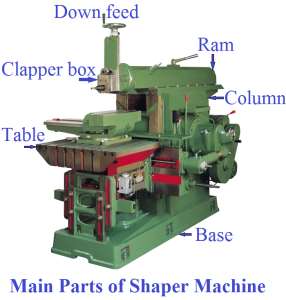
Parts of Shaper Machine
- The different parts of a standard shaper are:-
1. Base
2. Ram
3. Table
4. Saddle
5. Column
6. Cross rail
7. Tool head
1. Base
- The base is the necessary bed or support required for all machine tools.
- The base may be rigidly bolted to the floor of the shop or on the bench according to the size of the machine.
- It is so designed that it can take up the whole load of the machine and the forces set up by the cutting tool over the work.
- It is made of cast iron to oppose vibration and take up high compressive load.
2. Ram
- The ram is the reciprocating member of a shaper.
- This is semi- cylindrical in structure and heavily ribbed inside to make it more inflexible.
- It houses a screwed shaft for altering the position of the ram with regarding to the work and holds the tool head at the extreme forward end.
3. Table
- The table which is bolted to the saddle gets cross wise and vertical movements from the saddle and cross rail.
- It is a box like casting having T- openings both on the top and sides for clamping the work.
4. Saddle
- The saddle is mounted on the cross rail which holds the table immovably on its top.
- Crosswise movement of the saddle by rotating the cross feed screw by hand or force causes the table to move sideways.
5. Column
- The column is a box like casting which is mounted upon the base.
- The front vertical face of the column which serves as the guide ways for the cross rail is also accurately machined.
- The other side of the column contains levers, handles, etc. for operating the machine.
- It encloses the ram driving mechanism.
6. Cross rail
- The cross rail is mounted on the front vertical guide methods of the section.
- It has two equal guide ways on its top in the vertical plane that are perpendicular to the ram axis.
- The table may be raised or lowered to accommodate different sizes of the jobs by rotating an elevating screw which causes the cross rail to slide up and down on the vertical face of the column.
7. Tool head
- The tool head of a shaper holds the tool rigidly, gives vertical and angular feed movement of the tool and permits the tool to have an automatic relief during its return stroke.
- The vertical slide of the tool head has a swivel base which is hung on a circular seat on the ram.
Operations of Shaper Machine
- These are the operations that can be performed on shaper:-
1. Machining Vertical Surface
2. Machining Angular Surface
3. Machining Irregular Surface
4. Machining Horizontal Surface
5. Machining Splines or Cutting Gears
6. Cutting Slots, Grooves, and Keyways
1. Machining Vertical Surface
- A vertical cut is made while machining the finish of a work piece, squaring up a block or cutting shoulder.
- The work is mounted in the tight clamp or directly on the table and the surface to be machined is carefully aligned with the axis of the ram.
- A side cutting tool is set on the tool post and the position and length of stroke is changed.
- The vertical slide is set exactly at zero position and the apron is swivelled in a direction away from the surface being cut.
- This is important to enable the tool to move upwards and away from the work during return stroke.
- This holds the side of the tool from dragging on the planed vertical surface during return stroke.
- The down feed is given by turning the down feed screw by hand.
- The feed is about 0.25 mm given at the finish of each return stroke.
- Both roughing and finishing cuts are performed to finish the job.
2. Machining Angular Surface
- An angular cut is made at any angle other than a right angle to the flat or to the vertical plane.
- The work is set on the table and the vertical slide of the tool head is turned to the necessary angle either towards left or towards right from the vertical position.
- The apron is then further turned away from the work so that the tool will clear the work during return stroke.
- The down feed is given by turning the down feed screw.
- Angular surface can also be machined in a universal shaper or by utilizing a universal vise without turned the tool head.
3. Machining Irregular Surface
- Machining irregular surface means that a shaper can also produce a contoured surface, i.e. a convex or concave surface or a mix of any of the above surfaces.
- To produce a small contoured surface a forming tool is utilized.
- A round nose tool is selected for machining irregular surface.
4. Machining Horizontal Surface
- In horizontal operation, a shaper is mostly used to machine a flat, true surface on a workpiece held in a vise or other holding devices.
- The table is raised till there is a clearance of 25 to 30 mm between the work piece and tool.
- The length of stroke should be almost 20 mm longer than the work and the position of stroke is changed that the tool begins to move from a distance of 12 to 15 mm before the beginning of the cut and continues to move 5 to 8 mm after the end of the cut.
- The depth of cut for roughing work usually ranges from 1.5 to 3 mm, while for finishing work it ranges from 0.075 to 0.2 mm.
5. Machining Splines or Cutting Gears
- By using an index centre, a gear or equally spaced spline may be cut.
- The work is mounted between two centres and a spline is cut similar to the cutting of a keyway.
- The work is rotated after the first spline is cut through a predetermine amount by using the index plate and index pin.
- The periphery of a gear blank is divided, and equally spaced grooves are cut by using an index plate having proper hole circle.
- And formed tool is used for cutting gear.
6. Cutting Slots, Grooves, and Keyways
- With suitable tools a shaper can very conveniently machine slots or grooves on a work or cut outside keyways on shafts and interior keyways on pulleys or gears.
- For cutting slots or keyways a square nose tool similar to a parting tool is chosen.
- The diameter of the holes should be 0.5 to 0.8 mm oversize than the width of the keyway and the depth should be about 1.5 mm larger than the depth of the keyway.
- Lubrication is important on the work to prevent the cutting edge of the tool from wear due to hauling.
Size of Shaper Machine
- The size of a shaper is decide by the maximum length of stroke or cut it can make.
- The standard size goes from 175 to 900 mm.
- The length of stroke shows, in addition to the general size of the machine, the size of a 3D square that can be held and planed in the shaper.
- Consequently in a 250 mm shaper the length of stroke might be changed from 0 to 250 mm.
- The cross feed adjustment of the table will be 250 mm and the extreme bottom position of the cross rail will permit the table to accommodate a workpiece 250 mm high.
- The length of stroke of a shaper simply shows the general size of the shaper.
- Different points of interest, such as the type of drive, belt drive, or individual motor drive, power input, floor space required, weight of the machine, cutting to return stroke ratio, number and amount of feed, etc. are also sometimes necessary.
Advantages of Shaper Machine
- Less time and skill is required for setting of the work.
- The cost of machine is less.
- These are light in construction.
- These require less floor space area.
- The speed of shaper varies throughout of the work.
- The simple tool is used i.e. single cutting point tool.
Disadvantages of Shaper Machine
- Only one tool is used.
- Perfect accuracy is not obtained.
- There production rate is less.
- Only external surface will machined.
Application of Shaper Machine
- A shaper is used for machining small workpieces.
- It is mostly used for batch or job production.
- It is used to produce smooth, straight and flat surfaces.
- It is used for making internal splines, gear teeth, etc.
- They are also used for machining of die, punches, straight and curved slots.