Table of Contents
INTRODUCTION:
In the mechanical engineering field, the lathe machine plays an important role in manufacturing. In this article, I am going to discuss the lathe machine in detail.
A lathe machine is a versatile machine tool that rotates a workpiece about its own axis to give the desired shapes and sizes.
It is used to create cylindrical, conical, or threaded parts through operations like turning, facing, drilling, and boring.
The main function of a lathe machine is to shape raw materials into the desired form by removing excess material in the form of chips.
In a lathe machine, a single-point cutting tool is used where the movement of the tool is either parallel or perpendicular to the axis of rotation.
In a lathe machine, the workpiece rotates around a central axis, and a stationary or linearly moving cutting tool is fed into it to remove material.
And hence, this process allows the production of cylindrical, symmetrical, or complex shapes in materials through manual or CNC control.
The full form of ‘lathe’ is “Longitudinal Axis Tool Holding Equipment.”
Lathe machines are one of the most important machine tools that are used in the metalworking industry.
It is essential for producing turning, facing, drilling, and threading operations.
It is also known as “the mother/father of the entire tool family.”
It was invented by DAVID WILKINSON ( 05 Jan. 1771 – 03 Feb. 1852).

A lathe machine is a versatile power-driven tool used in manufacturing to shape metal, wood, or plastic by rotating a workpiece against a stationary cutting tool.
- A lathe machine is also known as “ Center Lathe ” because of two centers between which the job can be held and rotated.
Function of lathe Machine
- The main function of Lathe machine is to remove excess material in the form of chips by rotating the work piece against a stationary cutting tool.
- This is accomplished by holding the work securely and rigidly on the machine and then turning it against cutting tool which will remove metal from the work.
- To cut the material properly the tool should be harder than the material of the work piece, should be rigidly held on the machine and should be fed or progress in a definite way relative to the work.
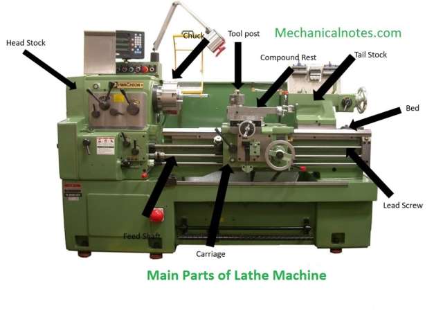
Main Parts of lathe Machine
- The main parts of lathe machine are as follows:-

Line Diagram: Main Parts of Lathe Machine
1. Bed
2. Head Stock
3. Main Spindle
4. Tail Stock
5. Lead Screw
6. Live Center
7. Dead Center
8. Carriage
i. Saddle
ii. Apron
iii. Tool Post
iv. Cross slide
v. Compound Rest
vi. Compound Slide
9. Feed Mechanism
i. Belt Feed Mechanism
ii. Gear Feed Mechanism
1. Bed
- The Bed forms the base of a machine.
- It is mounted on the legs of the lathe machine, which are bolted to the floor.
- It is made up of cast iron and its top surface is machined accurately and precisely.
2. Head Stock
- Head stock is an important part of a lathe machine, which is mounted permanently on the inner guide – ways at the left hand side of the bed.
- It consists of a main spindle, a chuck fitted at spindle nose, back gear drive and all gear drive.
3. Main Spindle
- A main spindle is a hollow cylindrical shaft.
- It’s face has a standard moarse taper.
- It is used for holding the live Centre or collet.
- The spindle rotates on two large bearings housed on the head stock casting.
- The front end of the spindle is threaded, those are used for holding the chuck, face plate, driving plate and catch plate.
- It is know as a spindle nose.
4. Tail Stock
- A tail stock is located on the inner guide – ways at the right side of the bed opposite to the head stock.
- The body of the tail stock is bored and house the tail stock spindle.
- The spindle moves front and back inside the hole.
- It has a taper hole to receive the dead Centre or shunk of tools such as drill or reamer.
- It’s body made up of cast iron.
5. Lead Screw
- It is used to transmit power to carriage through gear and clutch arrangement in the carriage apron.
6. Live Center
- A Live Center is mounting on bearings and rotates with the work.
- Live centers are using to hold or support a work-piece.
7. Dead Center
- A dead center may be use to support the work piece at either the fixed or rotating end of the machine.
- Dead centers are typically fully harden to prevent damage to the important mating surfaces of the taper and to preserve the 60° angle of the nose.
8. Carriage
- A carriage is located between the head stock and tail stock on the lathe bed guide – ways.
- It can be moved along the bed either towards or away from the head stock.
- It has several parts to support, move and control the cutting tool.

Image: Carriage
i. Saddle
- It is H – shaped casting.
- The saddle connects the pair of bed guide – ways as a bridge.

- It fits over the bed and slides along the bed between head stock and tail stock.
- The saddle can be moved by providing hand feed or automatic feed.
ii. Apron
- The front portion of a carriage call as apron. It consists of all control keys.

- The handle operates the carriage. It has a housing, which has a set of gears and split nut.
- Automatic feed and threading control are on the apron.
iii. Tool Post
- It is located on the top of the compound slide. It is used to hold the tools rigidly.
- Tools are selected according to the type of operation and mounted on the tool post and adjusted to a convenient working position.
- There are different types of tool post, which are as follows.
a. Single Way / Screw Tool Post
b. Four Way Tool Post
c. Quick Change Tool Post
d. British Type Tool Post
iv. Cross slide
- It is situated on the saddle and slides on the dovetail guide – ways at right angles to the bed guide – ways.

- It carries compound rest, compound slide and tool post.
- Cross slide hand wheel is rotated to move it at right angle to the lathe machine axis.
- The cross slide hand wheel is graduate on its rim to enable to give known amount of feed as accurate as 0.05 mm.
v. Compound Rest
- It is a part which connects to cross slide and compound slide.
- It is mounted on the cross slide by tongue and groove joint.

- The compound rest can be swiveled to the required angle while turning tapers.
- A top slide known as compound slide is attached to the compound rest by dovetail joint.
vi. Compound Slide
- Compound slide is a T -shaped rounded slot, which is fixed with cross slide upper surface by two bolts, which is related to a micrometer sleeve and screw handle with the outer edge of screw.
- Taper turning can be possible by setting the compound slide at half of a required angle.
- This slide is only used for less long job taper turning.
- The automatic feed is not possible in compound slide.
9. Feed Mechanism
- There are several mechanisms to make the carriage and cross slide move automatically to change the direction of their movement.
- Some important feed mechanisms are as follows:
i. Belt Feed Mechanism

- Belt feed mechanism is widely use in oldest lathe machines.
- In this, a cone stepped pulley is used for providing the different types of speed.
- To change the speed, a lever is used for sliding the belt at one pulley to another.
- Belt feed mechanism has a disadvantage of the belt slipping in pulley changing process.
ii. Gear Feed Mechanism

- In the gear feed mechanism, the power is transmitted from spindle to feed rod or lead screw by power gear train.
- Gear 1 is situated at the back side of the spindle and the tumbler bracket consists of the gears 2, 3, 4 and 5.
- A lever operate the bracket. This bracket is pivoted about the axis of the stud gear.
- This position of the bracket can be arrange in three different stages namely:
a. Neutral Position
b. Forward Position
c. Reverse Position
Working Principle of lathe machine
Principle
A lathe machine works on a simple principle where a workpiece is rotating along its center axis while a cutting tool removes material from the workpiece to give the desired shape and size.
- This rotation is achieved by mounting the workpiece between two supports or in a chuck or faceplate.

- When the tool is moved parallel to the work-piece then the cylindrical surface is formed.

- If the tool is moved inclined to the axis then it produces a tapered surface and so calls as taper turning.

Working
- It holds the work between two supports so call as centers.
- Face plate or Chuck are using for holding the work.
- Face plate or Chuck are mounted on the machine spindle.
- The cutting tool is holding with the help of Tool post.
- The movement of the job is rotating about the spindle axis.
- Against the revolving work, the tool is feed.
- The tool moves either parallel or inclination to the work axis.
Operations of Lathe Machine
- There are 13 operation that can be performed on the lathe:-

Image: Operation of Lathe Machine
1. Turning
i. Tapers and Taper Turning
ii. Straight turning
iii. Profiling
iv. External grooving, etc
2. Facing
3. Drilling
4. Boring
i. Counter Boring
ii. Taper Boring
5. Reaming
6. Knurling
7. Chamfering
8. Filling
9. Parting
10. Threading
11. Grooving
12. Forming
13. Polishing
1. Turning

- Turning is the operation of reducing the diameter of a work piece to produce a cone -shaped or a cylindrical surface as shown in fig. above.
- A simple single point cutting tools are use for turning operations.
- Turning can be different types like
i. Tapers and Taper Turning
ii. Straight turning
iii. Profiling
iv. External grooving, etc.
i. Tapers and Taper Turning
- A taper may be define as a uniform increase or decrease in diameter of a piece of work measured along its length.
- In a lathe, taper turning means to produce a conical surface by gradual reduction in diameter from a cylindrical work piece.
ii. Straight turning
- The Straight turning produces a cylindrical surface by removing excess metal from the work piece.
iii. Profiling
- In profiling, the cut can be vary with regard to cutting depth, feed and speed.
iv. External grooving
- In external turning operations machines the outer diameter of the work piece.
2. Facing

- Facing is an operation of reducing the length of a work piece to produce a flat surface square with the axis.
- A regular turning tool may also be using for facing a large work piece.
3. Drilling

- Drilling is an operation of producing a cylindrical hole in a work piece by the rotating cutting edge of a cutter known as the drill.
4. Boring

- Boring is the operation of enlarge a hole or cylindrical cavity to produce circular internal grooves.
- Holes may be bore straight and tapered.
i. Counter Boring
- Counter Boring is the operation of enlarging a hole through a certain distance from one end instead of enlarging the whole drilled surface.
ii. Taper Boring
- Taper Boring is similar to the external taper turning operation and is accomplished by rotating the work on chuck or a face plate, and feeding the tool at an angle to the axis of rotation of the work piece.
5. Reaming

- Reaming is the operation of finishing and sizing a hole which has been previously drilled or bored.
- The tool use so call as the reamer, which has multiple cutting edges.
6. Knurling

- Knurling is the process of embossing a diamond shaped pattern on the surface of a work piece.
- The purpose of knurling is to provide an effective gripping surface on a work piece to prevent it from slipping when operated by hand.
7. Chamfering

- Chamfering is the operation of beveling the extreme end of a work piece.
- This is done to remove the burrs, to protect the end of the work piece from being damaged and to have a better look.
8. Filling
- Filling is the finishing operation performed after turning.
- This is done in a lathe to remove burrs, sharp corners, and feed marks on a work piece and also to bring it to the size by removing very small amount of metal.
- The operation consists of passing a flat single cut file over the work piece which revolves at high speed.
9. Parting

- Parting is the operation of cutting a work piece after it has been machining to the desired size and shape.
- This process involves rotating the work piece on a chuck or face plate at half the speed that of turning and feeding by a narrow parting – off tool perpendicular to the axis by rotating the cross -slide screw by hand.
10. Threading

- Threading is a operations to produce a helical groove on a cylindrical or conical surface by feeding the tool longitudinally when the job is revolved between center’s or by a chuck.
- Threads can be produced either on internal or external surface of a cylindrical bar.
11. Grooving
- Grooving is the process of reducing the diameter of a work piece over a very narrow surface.
- It is often done at the end of a thread or adjacent to a shoulder to leave a small margin.
- Grooving Operations are:

a. Square Groove
b. Round Groove
c. Bevelled Groove
12. Forming

- Forming is the process of turning a convex, concave or of any irregular shape.
13. Polishing
- It is basically a surface finishing operation to improve the surface quality of the work piece.
- Polishing with successively finer grades of emery cloth after filling results in very smooth, bright surface.
Types of lathe machine
Lathe machines are classified according to their construction and design. Some of them are:
1. Bench lathe machine
2. Speed lathe machine
3. Engine lathe or center lathe machine
4. Tool room lathe machine
5. Capstan and turret lathe machine
6. Special purpose lathe machine
7. Automatic lathe machine
1. Bench lathe machine
- Bench lathe is a small lathe usually mounted on a bench.
- This is using for small and precision work.
2. Speed lathe machine
- Speed lathe is the simplest of all types of lathe in construction and operation.
- It consists of a bed , a head stock, a tail stock and a tool – post mounted on an adjustable slide.
- The spindle speed is about 4000 rpm.
- They named because of very High Speed of head stock spindle.
3. Engine lathe ( center lathe )
- The term ” engine ” is associated with the lathe which is early driven by steam engines.
- An engine lathe is also know as a reproductive machine because of its production capabilities.
- Engine lathes are an excellent tool, which aids in the creation of many modern tools.
Advantages
- It is using for mass production of products.
- It is using for manufacturing cylindrical shapes like steels and plastics.
Disadvantages
- It is very difficult to program in machine language.
- corruption, poor service, and racial issues.
4. Tool room lathe machine
- Tool room lathe is similar to an engine lathe.
- This lathe is mainly using for precision work on tools, Dies, Gauges and in making work where accuracy is necessary.
- It is used for making precision components in the tool room.
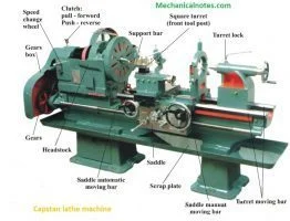
5. Capstan and turret lathe https://mechanicalnotes.com/capstan-and-turret-lathe-introduction-working-advantage-difference/
a. Capstan Lathe

- They having features of the basic lathe and have short slide tail stock.
- A Capstan machine is a processing machine uses for making the same parts again and again.
Advantages
- The production rate is high.
Disadvantages
- The heavier work-piece cannot machine by capstan lathe.
b. Turret Lathe
- The turret lathe is a form of metalworking lathe.
- It is used for repetitive production of duplicate parts.
- In a turret lathe, a longitudinally feed able, hexagon turret replaces the tail stock.
Advantages
- Turret lathe is using to machine the long and heavy workpieces.
- They having hexagonal tool post or head.
- There is no need of changing the tool.
Disadvantages
- They have manual indexes.
6. Special purpose lathe machine
- Special Purpose lathe are using for special purposes and for jobs which cannot be accommodated or conveniently machined on a standard lathe.
7. Automatic lathe machine
- In the automatic lathe, the various operations are automating like the change of the work piece.
- The working cycle is fully automatic that is repeated to produce duplicate parts without participation of operator.
Advantages
- During machine operation operator is free to operate another machine.
- More economy in floor space.
Disadvantages
- Lots of consideration are taking on fixing the setup.
Lathe Machine Accessories
- Lathe machine accessories are generally dividing into two categories :-
1. Work Holding device and
2. Cutting Tool Holding device
1. Work Holding device
- The work holding devices are the device that is using to hold and rotate the work pieces along with the spindle.
- The different work holding devices are using, according to the shape, length, diameter and weight of the work piece and the location of turning on the work. They are as follows :-
A. Chucks
- A chuck is a specialized types of clamp used to hold the work piece.
- Chuck is mounted on the spindle which rotates within the head stock.

Types of chucks:
- Three Jaw Chuck
- Four Jaw chuck
- Collect Chuck
- Spindle Chuck
- Magnetic Chuck
- Combination Chuck
- Air Operated Chuck
B. Face Plate

- Face plate is a circular disc and thread to fit to the nose of the lathe machine spindle.
- They having radial plain and ‘T’ – slots for holding the work by bolts and clamps.
C. Mandrels

- Mandrel is a device which uses for holding a hollow work piece.
- Mandrel is mounting between centers and work revolves with it .
D. Centers

- A lathe center is a tool that has ground to a point to accurately position a work piece.
- There are two centers :-
a. Live center
- A live center is a center which fits into the head stock spindle and revolves with the work.
- A live center is constructed so that the 60 degree center runs in its own bearing.
b. Dead center
- Dead center is the center which uses a tail stock spindle and doesn’t revolve.
c. Half center
- Half center is the center which is often used in the tail stock for facing up to or for Turning close to the end of the work .
- It cuts away almost to its point .
E. Driving Plate or Catch Plate

- Catch plate is plane disc which is made up of cast iron or steel.
- They having a central
F. Carriage

- Carriage is a device that Clamps around the work piece .
- They allow the rotary motion of the machines spindle to transmit the work piece.
- There are two types of carriage :-
a. Straight Tail Carriage
- This is using for driven the work by means of the pin provided in the driving plate .
b. Bent Tail Carriage
- It fits into the slot of the catch plate to drive the work .
c. Angle Vise

- Angle vise is an angular adjustment on base to allow operator to drill holes at an angle without tilting table .
2. Cutting Tool Holding device
- The cutting tool holding device is a device which is using to hold the cutting tools .
- The different cutting tool holding devices are as follows:-
A. Tool Post

- Tool Post is a device which holds the cutting tool on a lathe and some other machine.
B. Collect

- Collect is a device which is using to hold a cutting tool in the spindle of a milling machine.
C. Drill Chucks

- It is the most common devices which are using for holding straight-shank cutting tools.
- There are two common types:-
a. Key Type
- It has loosened or tightened by key.
b. Keys Less Types
- It has loosened or tightened by hand without the key.
D. Drill Sleeves

- Drill sleeves are used to adapt smaller Morse taper shank tools to larger machine spindles.
E. Drill Socket

- Drill socket is used to hold twist drills with shanks.
- They have used often an extension socket.
F. Straight Tool Holders

- Straight is using for taken cuts in either direction and for general machining operations.
Specifications of Lathe Machine:
- A lathe machine is basically specified by:-
1. Swing is the largest work diameter which can be swung for the lathe bed.
2. The distance between tailstock and headstock center.
3. Bed length of the machine in a meter ( m ).
4. The lead screw of the pitch.
5. The horse power of the machine.
6. Number of speed of HS spindle and speed range.
7. The machine weight in a tone.
Advantage of Lathe Machine
- There are 8 advantage of lathe machine:-
1. It gives greater production over a given period.
2. It is more economical in floor space.
3. It has low floor space and inventory maintenance requirements.
4. It has more constant flow of production.
5. It provides a precise and accurate result.
6. It has low scrap loss by reducing operator error.
7. During machine operation operator is free to operate another machine.
8. Semi skilled operators are enough.
Some keys points
1. Feed
- The rate at which the cutting tool crosses the work piece in the direction perpendicular to the work piece axis so calls as feed.
2. Depth of cut
- It is the perpendicular distance measured from the machined surface to the UN – cut surface of the work piece.
3. Cutting Speed
- The speed at which the metal is removing from the work piece with the help of tool so call as cutting speed.
Formula
Cutting Speed = πdn / 1000
4. Grinding
- Grinding is the operation of removing metal in the form of minute chips by feeding the work against a rotating abrasive wheel so call as Grinding wheel.

Very useful sir
Thanks..
Thanks so much sir. For posting such pleasant kind of information..
👍👍
Thanks…
Very useful notes of all students dear sir….
Thanks….