Table of Contents
Boring Machine
A boring machine is a type of machine tool that uses a rotating cutting tool or grinding wheel to enlarge existing holes in a workpiece or create new ones with precision.
- It is commonly used in manufacturing for precision hole creation and modification, often on large or complex parts.
- It can enhance the straightness, roundness, and surface quality of holes.
- Boring machines can handle parts that are difficult to rotate or have complex geometries.
- Boring can be performed manually or with CNC controls for greater precision and efficiency.
It has the capacity to increase the diameter of pre-drilled holes.
It is used to bore holes in large and heavy parts such as engine frames, steam engine cylinders, machine housings, borewell drilling, etc.
- It has vertical spindle where work- holding table can be moved horizontally in two directions that is perpendicular to each other.
- In the boring machine a rotating cutting tool or grinding wheel is used in the boring cutter.
- This boring cutter tool is made of M2 and M3 high-speed steel or P10 and P01 carbide.
- It was invented by John Wilkinson in 1775.
- Now a time, it is avaible with multiple spindles for their mass- production.
- Also, the styles, shapes and sizes of the boring machines are available in a large variety.
- It’s types are based on the position of boring tools, accuracy of the work required etc.
Definition of Boring Machine
- A boring machine is a type of machine tool that uses a rotating cutting tool or grinding wheel to create holes in a workpiece.
Types of Boring Machine
- These are the following types of boring machine:-
1. Table type boring machine
2. Floor type boring machine
3. Precision boring machine
4. Planer type boring machine
5. Multiple head type boring machine
6. Vertical turret lathe boring machine
7. Standard vertical boring machine
8. Vertical milling machine type boring machine
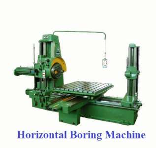
1. Table type boring machine
- The table type is the most common of all horizontal boring machines.
- This is so named because the work is mounted on the table which is adjustable and feed is given by hand power, lengthwise or crosswise with respect to the bed of the machine.
- The machine basically comprises of a bed, headstock supporting column, end supporting column, headstock, saddle and table, and boring bar.
- This type of machine may be suitable for general purpose work where other operations, in addition to boring, are required to be performed.
2. Floor type boring machine
- The floor type horizontal boring machine having no table uses a fixed floor plate on which T- spaces are given to hold the work.
- The headstock supporting column and the end supporting column and the end supporting column are mounted on the runways which are set at right angles to the spindle axis.
- This is so designed for holding very large and heavy workpiece which are difficult to be mounted and adjusted on a table.
3. Precision boring machine
- The precision boring machine uses single point tools to machine surfaces quickly and precisely.
- Cemented carbide and diamond tipped single point tools are worked at a very high cutting speed to produce accurately sized holes with a fine surface finish.
- The feeding movement might be given by the tool or by the work.
- The machine may be horizontal or vertical type.
4. Planer type boring machine
- It resembles the table type but table slides directly on the bed rather than on a saddle and reciprocates at right angles to the spindle similar to a planer.
- The end supporting column and headstock supporting column might be changed towards or away from the table for accommodating different widths of work.
- This type of machine is appropriate for supporting a long work.
5. Multiple head type boring machine
- This machine resembles a double housing planer or a Plano – miller.
- The table is supported on a long bed on which it responds.
- There are two vertical columns at different sides of the bed, almost at the center of the bed.
- The two columns are spanned by a cross rail.
- The machine may have two, three or four headstocks.
- This type of machine might be utilized both as a horizontal and vertical machine.
- The machining operations can be performed at the same time at various work surfaces.
6. Vertical turret lathe boring machine
- This kinds of boring machine combines the advantages of the vertical boring mill and the turret lathe.
- A vertical boring machine of smaller size is known as vertical turret lathe.
- It has an index able turret mounted upon the cross rail over the table for different tooling.
- The machine is suitable for boring and turning rail road wheels, piston rings, gear blanks etc.
7. Standard vertical boring machine
- This kinds of machines are larger in size than vertical turret lathe and there is no turret head.
- The machine is provided with two vertical heads and a couple of side heads.
- The machine is especially expected for boring large, cylindrical and symmetrical workpieces.
8. Vertical milling machine type boring machine
- This may be generate a horizontal flat surface, produce cylindrical turned surface, bore internal hole, perform cutting off, necking or forming operations, and generate internal or external taper surfaces.
- For machining a flat horizontal surface, the ram and the cross rail is locked at the desired position and the saddle is fed cross wise while the work revolves on the table.
Parts of Boring Machine
- These are the following parts of boring machine:-
1. Bed
2. Table
3. Housing
4. Cross rail
5. Boring bars
6. Tool head assembly
1. Bed
- The bed of a boring machine consists of a hollow circular casting grouted on the floor.
- The top of the bed is finished to provide a bearing surface for the table.
- It houses the spindle and a pinion for rotating the table.
2. Table
- The table which may be rotated is a circular casting mounted on the top of the bed.
- The horizontal surface of the table is finished and is provided with T -slots or chuck jaws for holding and clamping the work.
- Underside of the table may be provided with bevel gear teeth which meshes with a driving pinion.
- In large machines, a helical pinion meshes with a gear attached to the underside of the table.
3. Housing
- The housings are two vertical members which rise from the two sides of the bed.
- They are made of ribbed construction to ensure rigidity of the machine.
- The housings are joined at the top by a cross member.
- The vertical front face of the housings are accurately machined to form guide ways on which the cross rail slides.
4. Cross rail
- The cross rail is the horizontal member of the rectangular casting mounted on the two front faces of the housings.
- The cross rail may be moved up and down by rotating screws for accommodating different heights of work.
- The vertical front face of the housings are accurately finished for holding and sliding the saddle of the tool head.
5. Boring bars
- The boring bar supports the cutter for boring operations on jobs having huge bore distances across.
- For short holes the bar might be supported on the headstock spindle end only, whereas for long work the bar is supported on the spindle end and on the column bearing block.
6. Tool head assembly
- It comprises saddle, ram and tool post.
- The saddle is mounted on the cross rail and may be made to slide on it to generate flat horizontal surface by the tool.
- The ram holding the tool post may be made to slide up and down in the saddle perpendicular to the table to generate cylindrical surface or at an angle to the table surface to generate taper.
- The rams are also counter balanced for ease of operation.
Operations of Boring Machines
1. Boring operation
2. Forming operation
3. Machining flat surface
4. Taper boring operation
5. Turning cylindrical surface
6. Cutting off and necking operation
- In this operation holes are bored by using boring bars.
- Multiple holes may be bored one after another by changing the position of the workpiece and aligning it each time with the boring bar.
- To bore a hole, the boring bar is fitted to the spindle and the cutter is adjusted in the boring bar to the required dimension and a light cut is then taken.
- The bore is measured, required speed and feed adjusted and the cut is then completed.
2. Forming operation
- This operation is performed by cross feed movement of the saddle.
3. Machining flat surface
- For performing this operation, the cross rail and the ram is locked at the desired position.
- Then, the saddle is fed cross wise while the work revolves on the table.
- The depth of cut is given by the ram.
4. Taper boring operation
- The taper and conical surfaces are turned by swiveling the tool head to the required angle.
- When a conical surface having a large included angle which is beyond the range of the swiveling arrangement of the tool head is turned, a combined cross and down feed is applied simultaneously on the tool to cut the required taper.
5. Turning cylindrical surface
- In this activity, the saddle is clamped to prevent any horizontal movement of the ram, and the ram is fed downwards.
- The larger diameter holes are bored by feeding the tool head directly within the work and the smaller diameter holes are bored by using a boring bar attached to the tool head.
6. Cutting off and necking operation
- This operation is similar to the forming operation and it is also performed by cross feed movement of the saddle.
Sizes of Boring Machine
- The sizes of boring machines are varies according to their construction which may be vertical or horizontal.
For vertical
- The size is indicated by the diameter of its table or chuck expressed in mm.
- It can also be specified by the swing diameter of the largest work which can be accommodated in the machine.
- The size of a vertical turret lathe shifts from 600 to 2000 mm.
- The sizes of a standard vertical boring machine is pretty much as high as 6000 mm.
For horizontal
- The size is indicated by the diameter of its spindle in mm.
- The breadth of the spindle varies from 75 to 355 mm.
- To specify a boring machine fully other important dimensions for example spindle motor horse power, column heights, size of the table or size of the floor plate, spindle speeds, feeds and length of feeds, floor space required, weight of the machine, and so on likewise be expressed.
Mechanism of Boring Machine
- The mechanism of boring machine is based on a table type machine movements which are as follows:-
1. The end supporting block and the headstock might be moved down and up.
2. The spindle may be rotated with different speeds.
3. The spindle may be moved in or out by power or hand for feeding.
4. The saddle and the table may be moved by hand or power.
5. The columns might be moved by hand or force.
- All these movements which may be given independently or in combination.
- All the controls are housed in a particular position of the machine and the operator may give a closer attention to the work while controlling the machine.
Advantage of Boring Machine
- A boring machine creates accurate holes with a high degree of repeatability.
- It produces smooth surface finishes on the inside of holes.
- It has the ability to produce different shapes and sizes of holes.
- It is used on a variety of materials, like metal, wood, and plastic.
- It has the ability to produce a large quantity of machined parts in less time.
- It is used to cut materials quickly and may be able to make multiple cuts at once.
- It has less tool deflection.