Table of Contents
Introduction of Drilling Machine
A drilling machine is a powerful tool used to create cylindrical holes in solid materials.
It works by applying vertical pressure to a rotating cutting tool as it is pressed against a stationary workpiece.
- This rotating cutting tool is also called a twist drill.
- It rotates a drill bit at high speed, which cuts into the material and creates a clean hole.
- The machine consists of a motor, spindle, and feed mechanism to rotate and control the movement of the cutting tool against a stationary workpiece, which is clamped on a table.
Drilling machines are commonly used for various operations beyond just drilling, such as reaming, boring, counterboring, countersinking, and tapping.
- They offer efficiency, accuracy, and speed in various industries and DIY projects.
- It converts rotational power from a motor into vertical drilling action.
- Its spindle speed can be adjusted to match the material and bit size, according to 3ERP.
- It can perform a number of similar operations and may be drilled quickly and at a low cost.
- Today, many different types of drilling machines are available according to their requirements.
- The first holes were drilled by the Egyptians in 1200 B.C., about 300 years ago, with the help of a bow drill.
- The bow drill is the mother of the present-day metal-cutting drilling machine.
Definition of Drilling Machine
A drilling machine is a tool used to create cylindrical holes in solid materials like metal, wood, and plastic by rotating a cutting tool known as a drill bit.
- It removes the metal in the form of chips with the help of a rotating cutting tool.
Working of Drilling Machine
There are the following points to explain the working of the drilling machine:
1. The workpiece is clamped securely on the worktable.
2. An appropriate drill bit is fitted into the drill chuck, which is connected to the spindle.
3. An electric motor drives the spindle, causing the drill bit to rotate at a specific speed.
4. The operator then uses the feed mechanism to press the rotating drill bit against the workpiece.
5. The drill bit’s cutting edges shear off chips from the material, creating a hole of the desired depth and diameter.
6. And then the feed is stopped, and the drill bit is retracted from the workpiece.
Types of Drilling Machine
- These are 8 types of Drilling machines:-
1. Portable Drilling machine
2. Upright Drilling machine
3. Gang Drilling machine
4. Automatic Drilling machine
5. Sensitive Drilling machine
6. Radial Drilling machine
7. Multi Drilling machine
8. Deep hole Drilling machine
1. Portable Drilling machine
- This sort of Drill machine can be works easily anyplace in the workshop for boring gaps in workpieces in any position which can’t be bored in a standard Drilling machine.
- The engine is for the most part of all inclusive kind which might be driven by both A.C and D.C.
- The maximum size of the drill that it can accommodate is not more than 12 – 18 mm.
- The machine operates at high speed as smaller size drills are only used.
2. Upright Drilling machine
- It designed for handling medium size workpieces.
- An enormous number of axle speeds and feeds might be accessible for penetrating various kinds of work.

Image : Upright Drilling Machine
- The table of the machine additionally have various kinds of alterations.
- There are two general classes of it :-
i. Round column section or Pillar Drilling machine
- It consists of a round column that rises from the base which rests on the floor, an arm and a round table assembly, and a drill head assembly.
- The table and the arm might be moves in a circular segment upto 180° around the section and might be clipped at any position.
- The table may be rotates 360° about its own centre independent of the position of the arm for locating workpieces under the spindle.
- The maximum size of holes that the machine can bore isn’t in excess of 50 mm.
ii. Box column section Drilling machine
- It has the square table fitted on the slides at the front face of the machine column.
- Heavy box column gives the machine strength and unbending nature.
- The table is raised or brought down by a hoisting screw that gives extra help to the table.
- These unique highlights license the machine to work with heavier workpieces, and gaps in excess of 50 mm in distance across.
3. Gang Drilling machine
- It is a machine where various single axle drill machine segment are put next to each other on a typical base and have a typical worktable
- It has four to six spindles may be side by side.
- A series of operations may be performed on the work by spindle shifting the work from one position to the other on the work table.
- The speed and feed of the spindles are control independently.
4. Automatic Drilling machine
- It can play out a progression of machining tasks at progressive units and move the work from one unit to the next naturally.
- This kind of machine is planned only for generation purposes might be utilized for processing, Honing and comparative activities notwithstanding boring and tapping.
5. Sensitive Drilling machine
- This is a small machine design for drilling a small holes at high speed in light jobs.
- The base of the machine may mount on a bench or on the floor.

Image : Sensitive Drilling machine
- It comprises of a vertical section, a level table, a head supporting the engine and driving instrument, and a vertical shaft for driving and turning the drill.
- There is no course of action for any programmed feed of the drill shaft.
- Its capable of rotating drills of diameter from 1.5 – 15.5 mm.
6. Radial Drilling machine
- It intended for drilling medium to large and heavy workpieces.
- It comprises of a substantial, round, vertical section mounted on an enormous base.
- The segment bolsters an outspread arm which can be raised and brought down to suit workpieces of various stature.
7. Multi Drilling machine
- Its main function is to drill a number of holes in a piece of work.

Image : Multiple Spindle Drilling Machine
- Also to reproduce the same pattern of holes in a number of identical pieces in a mass production work.
8. Deep hole Drilling machine
- In this machine, special machines and drills are use for drilling deep holes in rifle barrels, crank shafts, long shafts, etc.
- A long activity is typically bolstered at a few focuses to forestall any redirection.
- The machine may be horizontal or vertical type.
Also Read
Lathe machine- Introduction, Parts, Operation, Working Principle.
Milling machine – Definition, Types, Parts, Operation.
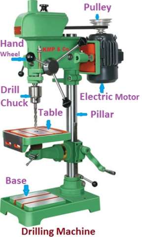
Parts of Drilling Machine
- These are the following major parts of the Drilling machine:-

1. Head
2. Spindle
3. Drill chuck
4. Table
5. Base
6. Column
1. Head
- It is mounted on the highest point of the segment and houses the driving and encouraging component for the axle.
2. Spindle
- This is taper shaft in circular shape which helps to hold the drill chuck.
- Its made up of high carbon chromium steel, stainless steel or steel alloys.
- They transfer the rotary motion from drill head to drill jigs.
- It can move up and down with the help of rack and pinion mechanism.
3. Drill chuck
- It is generally self – centering which is made of special alloy steel.
- Its present on the lower end of the spindle.
4. Table
- Its present on the column with T -slots for clamping the work directly on its face.
- They may be round or rectangular in shape.
5. Base
- It is that part of a machine on which vertical column is present.
- Its support the column and worktable with other attachments.
- It made up of casting.
6. Column
- It is the vertical member of the machine that supports the table and the head containing all the driving mechanism.
- It may be made of box section or of round section.
- Box column is more rigid unit.
- In Box column type, the front face of the column is accurately machine to form guideways on which the table can slide up and down for vertical adjustment.
- In the round segment rack teeth are cut on the essence of the segment for vertical development of the arm and the table.
Operation of Drilling Machine
- These are the following various operations that can be performed in a drilling machine:-
1. Drilling operation
2. Boring operation
3. Reaming operation
4. Counter Boring operation
5. Counter Sinking operation
6. Spot Facing operation
7. Tapping operation
8. Lapping operation
9. Grinding operation
10. Trepanning operation

Image : Operation of Drilling Machine
1. Drilling operation
- Drilling is an operation of producing a cylindrical hole by removing metal by rotating edge of cutting tool call as Drill.

Image : Drilling Operation
- This is one of the simplest methods of producing a hole.
- It doesn’t produce an accurate hole in a workpiece due to the vibration of the spindle and drill.
2. Boring operation
- The purpose of boring is to enlarge a hole by means of an adjustable cutting tool with only one cutting edge.
- It machine the internal surface of a hole already produced in casting.
- To correct out of roundness of the hole.
- To address the area of the gap as the drilling apparatus follows an autonomous way as for the gap.
3. Reaming operation
- It is a precise method for estimating and completing an opening which has been recently bored.
- The tool uses for reaming is known as the reamer which has multiple cutting edges.
- It can’t originate a hole.

- It basically follows the way which has been recently bored and expels an extremely limited quantity of metal.
- The material removes through this process is around 0.375 mm and for accurate work this should not exceed 0.125 mm.
4. Counter Boring operation
- This is an operation of enlarging the end of a hole cylindrically.

- The enlarged hole forms a square shoulder with the first gap.
- The cutting speed for this operation is 25 % less than that of drilling.
5. Counter Sinking operation
- It is an activity of making a cone – shaped enlargement of the end of a hole to provide a recess for a flat head screw or countersunk rivet fitted into the hole.

- The standard countersinks have 60°, 82° or 90° included angle and the cutting edges of the tool are formed at the conical surface.
6. Spot Facing operation
- This is an operation of smoothing and squaring the surface around a hole for the seat for a nut or the head of a screw.

- A counter bore or an extraordinary spot confronting apparatus might be utilized for this reason.
7. Tapping operation
- This is an operation of cutting internal threads by means of cutting tool called a tap.
- A tap might be considered as a jolt with precise strings cut on it.

- The threads act as cutting edges which are solidified and ground.
- It removes metal and cuts internal threads which will fit into outer threads of the same size.
8. Lapping operation
- This is an operation of sizing and finishing a small diameter hole already hardened by removing a very small amount of material by using a lap.
- The lap fits in the hole and moves up and down while it revolves.
9. Grinding operation
- It is an operation to finish a hardened hole.
- The grinding wheel is made to rotate with the shaft and is exhausted and down.
- The accuracy in grinding operation is quite high about ± 0.1125 mm.
10. Trepanning operation
- This is an operation of producing a hole by removing metal along the circumference of a hollow cutting tool.
- It performs for producing large holes.

- The tool resembles a hollow tube having cutting edges at one end and a strong shank at the other to fit into the drill spindle.
- This is one of the effective strategies for delivering a hole.
Drilling Machine tools
1. Drill Tool
- A Drill is a fluted cutting tool used to originate or enlarge a hole in a strong material.
- It manufactures in a wide variety of types and sizes.
- The types of the drill commonly use :
i. Flat or Spade Drill
ii. Straight Fluted Drill
iii. Two Lip Twist Drill
iv. Taper Shank Core Drill
v. Oil Tube Drill
vi. Centre Drill
i. Flat or Spade Drill
- A flat drill is sometimes used when an equivalent sized twist drill is not available.
- It is usually made from a piece of round tool steel which is forge to shape and ground to size.
- The cutting edge differs from 90° – 120° and alleviation or leeway at the forefront is 3° – 8°.
Disadvantages
- This types of drill is that each time the drill is ground the diameter is reduced.
- It can’t be relief upon to drill a true straight hole, since the point of the drill has a tendency to run out of the center.
- The chips don’t come out from the hole automatically, but tends to pack more or less tightly.
ii. Straight Fluted Drill
- It has grooves or flutes running corresponding to the drill axis.
- This may be consider as a cutting tool having zero rake.

Image : Straight Fluted Drill
- Its inconvenient in standard practice as the chips don’t come out from the hole automatically.
- Its mainly use in drilling Brass, Copper, or other softer materials.
iii. Two Lip Twist Drill
- It was initially made by twisting a flat piece of tool steel longitudinally for several revolutions, then grinding the diameter and the point.
- The present day twist drills are made by machining two spiral flutes or grooves that run longwise around the body of the drill.
- Twist drill is end cutting tool.
- Different types of twist drills are:
a. Parallel Shank Jobbers Twist Drill
b. Parallel Shank Stub Series Twist Drill
c. Parallel Shank Long Series Twist Drill
d. Taper Shank Twist Drill
a. Parallel Shank Jobbers Twist Drill
- The Drill has two helical flutes with an equal shank of around a similar width as the cutting end.
- The diameter of the drill range from 0.2 – 16 mm increasing by 0.02 – 0.03 mm in lower arrangement to 0.25 mm in higher arrangement.
b. Parallel Shank Stub Series Twist Drill
- The drill is a shortened form of the equal shank twist drill, the shortening being on the flute length.

Image : Parallel Shank Stub
- The diameter of the drill ranges from 0.5 – 40 mm increasing by 0.3 mm in lower series to 0.25 – 0.5 mm in higher series.
c. Parallel Shank Long Series Twist Drill
- It has two helical flutes with a parallel shank of approximately the shank diameter as the cutting end.
- The overall length of this drill is the same as that of a taper shank twist drill of corresponding diameter.
- The diameter varies from 1.5 – 26 mm increasing by 0.3 mm in lower series to 0.25 mm in higher series.
d. Taper Shank Twist Drill
- It has two helical flutes with a taper shank for holding and driving the drill.
- The shank for these drills conform to Morse tapers.
- The diameter ranges from 3 – 100 mm.
- The diameter increases by 0.3 mm in lowest series having Morse taper shank.
iv. Taper Shank Core Drill
- These drills are planned for broadening cored, punched or penetrated gaps.
- These drills can’t originate a hole in solid material because the cutting edges don’t extend to the center of the drill.
- The metal is remove by a chamfered edge at the end of each flute.
- The cutting action of a core drill is like to that of a rose reamer and it is regularly utilized as a roughing reamer.
v. Oil Tube Drill
- It used for drilling deep holes.
- This run lengthwise spirally through the body to carry oil directly to the cutting edges.
vi. Centre Drill

Image : Center Drill
- These are straight shank, two fluted twist drills used when centre holes are drilled on the ends of a shaft.
- They are made in finer sizes.
Geometry of a Twist Drill
- These are the following geometry of a twist drill:-
1. Body
2. Flutes
3. Shank
4. Lips
5. Webs
6. Margin
7. Dead Centre
8. Lip relief angle
9. Point Angle
10. Helix Angle
11. Chisel Edge Angle

Image : Geometry of a Twist Drill
1. Body
- It is the piece of the drill that is fluted and eased.
2. Flutes
- It forms the cutting edges on the point.
- To allow the chips to escape.
- To cause the chips to curl.
- They permit the cutting fluid to reach the cutting edges.
3. Shank
- It is that part of the drill which fits to the holding device.
4. Lips
- It is the main cutting edges of the drill.
5. Webs
- It is the metal column in the drill to separate the flutes.
6. Margin
- It is the thin surface along the depression that decides the size of the drill and keeps the drill adjusted.
7. Dead Centre
- It is a sharp edge at the tip end of the drill.
8. Lip relief angle
- This is the axial relief angle at the outer corner of the lip.
9. Point Angle
- This is the angle includes between the cutting lips projected upon a plane parallel to the drill axis and parallel to the cutting lips.
10. Helix Angle
- It decides the rake edge of the front line of the drill.
11. Chisel Edge Angle
- It is the angle between the chisel edge and the cutting lip.
Work Holding Device of Drilling Machine
- These are the following devices that can be commonly used for holding the work in a Drilling Machine:-
1. T -bolt and Clamps
2. Drill Press Vise
3. Step Block
4. V -Block
5. Angle Plate
6. Drill Jigs
1. T -bolt and Clamps
- This is one of the most common methods holding the work directly on the drilling machine table is by means of T -bolt and Clamps.
- The diameter of T -bolts usually ranges from 15 – 20 mm.

Image : T -bolt
- The clamp or straps are made of mild steel flats 12 – 20 mm thick and 45 – 70 mm wide.
- Some of the common types of clamps are as follows :
i. Plain Slot Clamp
- These are made of mild steel at having a central slot through which a T -bolt is made to pass.
ii. Goose Neck Clamp
- This is use for holding work of sufficient height.
- The clamps are sufficiently strong and are usually manufactured by forging.
iii. U -Clamp

Image : U Clamp
- Its very useful for quick adjustment of the work.
- The clamp can be remove without removing the nut.
iv. Finger Clamp
- They have a round or flat extension which may be fitted in a hole of the workpiece for clamping.
v. Adjustable Step Clamp

Image : Adjustable Step Clamp
- It has a screw at its one end which is used to level the clamp when its other end rests against the work.
2. Drill Press Vise
- This is one of the most common methods of holding small and regular shaped workpieces.
- This may be plain or universal type.
- In a universal vise the base may be swiveled at any angle about the vertical axis and it may be tilted in a vertical plane to drill hole in a work at different angles.
3. Step Block
- This is used in conjunction with T -bolts and clamps for holding the work directly on the table.
- Its provide support for the other end of the clamp.
- They made of mild steel.
4. V -Block
- Its use for holding round workpieces.
- They are accurately machined cast iron or steel blocks.
5. Angle Plate

Image : Angle Plate
- These are usually made of cast iron having two faces at right angles to each other.
- Its use when it is necessary to drill a hole parallel to another surface.
6. Drill Jigs
- Its use for holding the work in a mass production process.
- It can hold the work safely, find the work, and guide the device at any ideal position.
Tool Holding Devices
- These are the following different methods which are used for holding tools in a drill spindle:-
1. Directly Holding Tool
2. Sleeve
3. Socket
4. Drill Chucks
5. Special Attachments
1. Directly Holding Tool
- All general purpose drilling machines have the spindle bored out to a standard taper to receive the taper shank of the tool.
- The taper use in a drill spindle is usually Morse standard taper which is approximately 1: 20.
- The tool may be removed by pressing a tapered wedge known as the drift into the slotted hole of the spindle.
2. Sleeve
- The sleeve fits into the taper hole of the spindle and holds tool shanks of smaller sizes in the taper hole.
- It has flat end or tang which fits into the slot of the spindle.
- The sleeve with the device might be evacuated by compelling a float inside the opening of the axle and the device might be independent from the sleeve by the comparable procedure.
3. Socket
- Drill attachments are any longer in size than the drill sleeves.
- It consists of a solid shank attachment to the end of a cylindrical body.
- The decrease shank of the attachment fits in with the decrease of the drill axle and fits into it.
4. Drill Chucks
- It has taper shanks which fits into the drill machine spindle.
- They are especially intended for holding smaller size drills or any other tools.
Applications of Drilling Machine
- It use in the field of industries purpose like manufacturing, metalworking, etc,.
- It use for producing holes like drilling, boring, etc,.
- They also use in underground mining purpose.
- Use for the purpose of under cutting.
Advantages of Drilling Machine
- It requires less labor.
- It gives high precision and accuracy.
- No skill operators are required.
- It consumes less floor area.
Disadvantages of Drilling Machine
- It produces lots of torque at low speeds.
- It is not suitable for small production methods.
For better understanding watch this video clip
https://www.youtube.com/watch?v=DvfmRV84Jus

Excellent work sir.
Thanks u sir…
Thanks….
Very useful sir 👍👍🤗
Thanks…
Very good 👍
Thanx.