Table of Contents
Introduction to Milling Machine
A milling machine is a versatile machining tool used in manufacturing to shape solid materials by using a rotating, multi-point cutting tool to create precise shapes and features.
- It is a key piece of equipment used in manufacturing for creating a wide range of parts and components with flat, contoured, and other complex surfaces.
- The core of a milling machine is its rotating cutter that removes material from a workpiece as it rotates and moves against the workpiece.
- The milling cutter comes in various shapes and sizes that are mounted on the machine’s spindle and rotate at high speeds.
- This machine allows for precise control of the movement of the workpiece in all three axes (X, Y, and Z), enabling the creation of complex geometries.
- Milling machines are used in industries like aerospace, automotive, medical, and more to produce a wide range of components.
- This machine also used for producing drilling, boring, cutting gears, threads, slots, and shaping flat and irregularly shaped surfaces in various materials.
- These materials may be metals, plastic, and wood.
- This machine can also hold one or more number of cutters at a time.
- It is superior to other machines as regards accuracy and better surface finish, and is designed for machining a variety of tool room work.
- This machine can be operated manually or with CNC control for precise and automated operations.
- The 1st milling machine came into existence in about 1770 and was of French origin.
- The milling cutter was 1st developed by Jacques de Vaucanson in year 1782.
Definition of Milling Machine
- A milling machine is a versatile tool that removes unwanted material from a workpiece by rotating a multi-point cutting tool.
- This may be done varying direction at an angle with the axis, cutter head speed, and pressure.
- Milling can be done with wide range of machine tools.
Also read:
- Lathe machine:- Introduction, Definition, Parts, Types, Operations, etc.
- Capstan lathe:- Introduction, Differences, Working Principle, etc.
- Heat treatment:- Definition, Types, Methods, etc.
Principal & Working of Milling Machine
Principal
- A milling machine principal states that it removes material from a workpiece using a rotating cutter with multiple cutting edges.
In this operation, the workpiece is fed against the rotating cutter, and the teeth of the cutter remove material to create the desired shape.
- The work piece or jobs are fixed on the work table and feed is given against the tool.
The table can be given three type of movements:
1. Longitudinal cross wise
2. Vertical movements
3. Rotational movements

Fig. Working -Principle
Working
- The work is rigidly clamped on the table of the machine and multi teeth cutter will revolving either on a spindle.
- The cutter has many cutting edges and is rotated at high speeds.
- The work can be fed in a longitudinal, vertical, or cross direction.
- For further process, the cutter teeth remove the metal from the work surface to produce desired shape like flat, circular, or curved.
Main Parts of Milling Machine
- There are 10 main parts of a milling machine, which are named as:-

Image. Main Parts of Milling ( Machine )
1. Base
2. Column
3. Knee
4. Saddle
5. Table
6. Spindle
7. Over Arm
8. Arbor
9. Ram
10. Power Feed Mechanism
1. Base
- The base is the foundation and lowermost part of the machine that’s providing stability and support.
- It is a dim iron throwing precisely machined on its top and base surface and fills in as an establishment part for the various parts which rest upon it.
2. Column
- It is the vertical part that is fixed on the base.
- The segment is box formed, vigorously ribbed inside and houses all the driving instruments for the shaft and table feed.
- Front vertical face of column is provided with a vertical slide which can be square or of dovetail type.
- The knee is made of cast iron which slides up and down on the vertical slide ( guide ways ) on the face of column.
3. Knee
- The knee is an unbending dark iron throwing that slides all over on the vertical methods for the section face.
- The knee houses the feed system of the table, and various controls to work it.
- The top essence of the knee shapes a slide route for the seat to give cross travel of the table.
4. Saddle
- Saddle is present on the knee which supports the table.
- It is proving motion in the X and Y axes by means of lead screw.
5. Table
- The table is present on the top of the saddle and can be moved along the X axes.
- It contains several T – slots for the mounting of work piece or clamping jigs & fixtures.
6. Spindle
- Spindle is the hollow shaft that is use to hold and drives the cutting tools.
- The face of the spindle that lies near to the table has an internal taper machined on it.
7. Over Arm
- It is a horizontal beam which present at the top face of the column.
- This may be a single casting which slides on the top face of the column.
- It might comprise of a couple of tube shaped bars that slide through the openings in the segment.
8. Arbor
- The arbor has an oil reservoir that lubricates the the bearing surfaces.
- It prevents the spring of outer end of the arbor during cutting operations.
- Arbor also helps in aligning the outer end of the arbor with the spindle.
9. Ram
- The smash on which the processing head is connected can be situated ahead and in reverse along the slide route on the highest point of the section.
4. Power Feed Mechanism
- It is the knee which contains the force feed component.
- It’s use to control the longitudinal ( left & right ), transverse ( in & out ) and vertical ( up & down ) feeds.
Operation of Milling Machine
- These are the following different operations that can be performed in the milling machine:-
1. Face milling operation
- This is an operation for producing a flat surface, which is perpendicular to the axis of rotating cutter.

- The operation is perform by the face milling cutter.
2. Plain milling operation
- It is the operation of production of a plain, flat, horizontal surface parallel to the axis of rotation.

- It is also call as slab or surface milling.
- A plain milling cutter is use.
3. End milling operation
- It is the operation of production of flat surface which may be vertical, horizontal or at an angle in reference to the table surface.
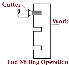
- End mill cutter is use.
- There cutters are using for production of slots, grooves or key ways.
4. Side milling operation
- It is the machining process which produces flat vertical surface at the sides of a work piece.
5. Slot milling operation
- This is a operation of producing slots like T– slots, Plain- slots etc.
6. Angular milling operation

- It is the operation of producing all types of angular cuts like V- notches, grooves, serrations and angular surfaces.
- E.g. Production of V- Blocks, etc.
7. Form milling operation
- This is the process of machining special contour ( outline ) composed of curves, straight lines, or entirely of curves at a single cut.

- This operation is accomplish by using convex, concave and corner rounding milling cutters.
- In the wake of machining, the shaped surface is checked by a layout measure.
8. Straddle milling operation
- It is a process in which two side cutters are use to machining two opposite sides of a work piece simultaneously.

- The Straddle milling is very common to produce square or hexagonal surfaces.
9. Gang milling operation

- It is the machining process in which two or more milling cutters are use together to perform different operations simultaneously.
10. Profile milling operation

- It is the operation of reproduction of an outline of a template or complex shape of a master die on a work piece.
11. Saw milling operation

- The Saw milling is the operation of production of a narrow slots or grooves on a work piece by using a saw milling cutter.
12. Gear milling operation
- The gear cutting operation is performed in a milling machine by using a form relieved cutter.
- The cutter may be cylindrical type or end mill type. The cutter profile corresponds exactly with the tooth space of the gear.

- Similarly separated rigging teeth are cut on an apparatus clear by holding the work on an all inclusive isolating head and afterward ordering it.
13. Helical milling operation
- The helical milling is the operation of production of helical flutes or grooves around the periphery of a cylindrical or conical work piece.

- The usual examples of work performed by helical milling operations are : Production of helical milling cutters, helical gears, cutting helical grooves or flutes on a drill blank or a reamer.
14. Cam milling operation
- The Cam milling is the operation of production of cams in a milling machine by the use of a universal dividing head and a vertical milling attachment.
- The axis of the cam can be set from zero to ninety degrees in reference to the surface of the table for obtaining different rise of the cam.
- The cams are used to open and close of valves in the internal combustion engines.
15. Thread milling operation
- The thread milling is operation of production of threads by using a single or multiple threads milling cutter.

- The operation is performed in special thread milling machines to produce accurate threads in small or large quantities.
Types of Milling Machine
- According to their general design there are the following classification or types of milling machine:-
1. Column and knee type
a. Hand milling machine
b. Plain ( Horizontal ) milling machine
c. Universal milling machine
d. Omniversal milling machine
e. Vertical milling machine
2. Manufacturing of fixed bed type
a. Simplex milling ( machine )
b. Duplex milling ( machine )
c. Triplex milling ( machine )
3. Planer type
4. Special type
a. Rotary table milling ( machine )
b. Drum milling ( machine )
c. Planetary milling ( machine )
d. Pantograph, Profiling & Tracer controlled milling ( machine )
1. Column and knee type

Image: Column & Knee type
- It is most commonly used in general shop-work.
- The column and knee type milling machine are classified according to the various methods of supplying power to the table, different movements of the table and different axis of rotation of the main spindle.
a. Hand milling ( machine )
- In Hand milling, the feeding movement of the table is supplie by hand power.
- The machine is relatively smaller in size than that of other types and is particularly suitable for light and simple milling operations such as machining slots, grooves, and key ways.
b. Plain ( Horizontal ) milling machine
- It is the simplest form of milling ( machine ).
- In this milling, the work piece can be fed in all three axes and this process is suitable for short production.
- In this milling heavy work piece cannot machined and the operation is slow because of large number of controls.
c. Universal milling machine
- It is similar to the horizontal milling but the table is placed on the swivel and swivel is placed on the saddle.
- The machine can be produce spur, spiral, bevel gears, twist drills, reamers, milling cutters, etc. besides doing all conventional milling operations.
d. Omniversal milling machine
- In this machine, all the movements of a universal milling machine, can be tilted in a vertical plane by providing a swivel arrangement at the knee besides the table.
e. Vertical milling machine
- In this machine, cutter spindle have vertical position and the table movements are horizontal, vertical and transverse.
- In vertical milling, over arm is small and provides a strong support for the spindle and spindle can be moves up and down to perform the operations like grooving, facing etc.
2. Manufacturing of fixed bed type
- The fixed bed type milling are comparatively large, heavy, and rigid and differ radically from column and knee type by the construction of its table mounting.
- The table movement is restricted to reciprocation at right angles to the spindle axis with no provision for cross or vertical adjustment.
- The shaper mounted on the axle head might be moved vertically on the section, and the axle might be balanced on a level plane.
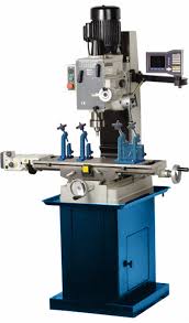
a. Simplex milling machine
Source: mte.us.com
- In the simplex machine, the spindle head or the spindle can travel only in one direction.
- Mostly, it travels in vertical direction.
b. Duplex milling machine

Image Source: Indiamart.com
- In this machine, the shaft can travel both vertical and flat way.
c. Triplex milling machine
- In triplex machine, the spindle can move in all three direction along X, Y and Z, axis.
3. Planer type
- It’s mostly use for facing operation in mass production.
- These machine is similar to the bed type milling except it can mounted with various cutters and spindle heads to the machine.

Source: Indiamart.com
- These cutters can perform the facing operations simultaneously.
4. Special type
- These machines are the modern milling machines which are developed to easy the milling operations according to the job.
- Following are the special type of milling machines are:
a. Rotary table milling machine
- This is the modification of a vertical machine for the machining of flat surfaces at production rate.
- The cutter may be set at different heights relative to the work so that when one of the cutter is roughing the pieces, the other is finishing them.
b. Drum milling machine
- It’s use for production work only.
- This type of machine has a vertical central drum which rotates on a horizontal axis much like a Ferry’s wheel.
- In activity, the drum – apparatus turns gradually, conveying the neutralize the pivoting cutters.
c. Planetary milling machine
- In this machine, the work is held stationary while the cutters move in a planetary path to finish a cylindrical surface on the work either internally or externally or simultaneously.
d. Pantograph, Profiling & Tracer controlled milling machine
- Pantograph
- A pantograph is a mechanism that is generally constructed of four bars or links which are joined in the form of a parallelogram.
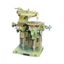
Image Source: Indiamart.com
- It twists so as to enable a client to draw a picture while at the same time drawing at least two duplicates of it..
- Profiling
- A profiling machine duplicates the full size of the template attached to the machine.
- This is practically a vertical milling machine of bed type in which the spindle can be adjusted vertically and the cutter head horizontally across the table.
- The movement of the cutter is regulated by a hardened guide pin.
- Tracer controlled
- The tracer controlled milling machine reproduces irregular or complex shapes of dies, moulds, etc, by synchronized movements of the cutter and tracing element.
Methods of Milling Machine
There are two basic methods of milling machine that can be performed:-
1. Up milling or conventional milling
2. Down milling or climb milling
1. Up milling or conventional milling
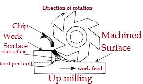
- The Up milling is also call as conventional milling.
- In an Up milling process, the direction of cutter rotation is opposite to that of feed motion.
- If cutter rotates clockwise, the feed motion will take place in rightward direction.
- The chip thickness is least toward the beginning of the cut and most extreme toward the end.
- Slicing power shifts from zero to the most extreme worth.
Advantages of Up milling
- The cutter is not affected by the sandy surfaces of the work piece.
- It doesn’t require backlash eliminator.
- Built up edge ( BUE ) fragments are not available on the machining surface.
- The loads on the teeth are acting gradually.
Disadvantages
- The propensity of slicing power to lift the work from the installations and poor surface completion.
2. Down milling or climb milling

- It is also know as climb milling.
- In down milling, the work piece cuts from right to left cutter rotation in clockwise direction.
- The chip thickness is maximum at the start of the cut and minimum in the end.
- There is less friction involves and consequently less heat is generated on the contact surface of the cutter and work piece.
Advantages
- Tool blunting is less.
- It produces better surface finish.
- The flat work piece can be machining easily.
- It is characterized by less tendencies of chattering and vibration.
- The fixture are simple and less costly.
Disadvantages
- The chip thickness is maximum at the point of tooth contact with the work piece.
Difference between Up milling & Down milling
| S.NO. | Up Milling | Down Milling |
| 1. | It is also known as conventional milling. | It is also known as climb milling. |
| 2. | In this milling, the cutter rotates against direction of feed. | In this milling, the cutter rotates with direction of feed. |
| 3. | The width size of the chip is zero at initial cut and increase with feed. This will maximum at the end of feed. | The size of the chip is maximum at start of cut and decrease with the feed. This will zero at the end of feed. |
| 4. | The tool wear rate is more because tool runs against the feed. | The tool wear rate is less because the cutter rotates with feed. |
| 5. | The cutting chips fall down in front of the cutting tool. | The cutting chips fall down behind the tool. |
| 6. | It gives less surface finish. | It gives better surface finish. |
| 7. | The cutting chips are carried upward with the help of tool. | The cutting chips are carried downward with the help of the tool. |
| 8. | The heat is diffuse to the work piece which causes the change in metal properties. | The heat is diffuse to the chip does not change the work piece properties. |
| 9. | Tool life is less. | Tool life is more. |
| 10. | This is also famous as traditional way of cutting the surface. | This is non – traditional way of cutting the work piece. |
| 11. | The high quality cutting fluid is used. | The simple cutting fluid is used. |
| 12. | Because of upward force by tool, high strength jig and fixture are used. | Because of downward force by tool, normal jig and fixture are used. |
| 13. | It requires high cutting force. | It requires low cutting force. |
| 14. | The cutting forces act upward. | The cutting forces act downward. |
| 15. | It is mostly applicable for cutting of brass, bronze and ferrous materials. | It is mostly applicable for aluminium and aluminium alloys. |
Types of Milling cutters
- A milling cutter is a cutting tool of milling machine, which are available in many shapes and standards.
- The teeth may be straight or at a helix angle and helix angle helps milling cutter for a slow engagement of the tool to distribute the forces.
There are following wide ranges of milling cutters:-
1. Plain cutters
2. End mills
3. Face mill
4. Slab mill
5. Hollow mills
6. Metal slitting saws
7. Side and face cutter
8. Cylindrical side and face slotting, screw slotting
9. Single, double and equal angle cutters
10. T -slot, dovetail, convex, single and double corner rounding cutters
1. Plain cutters
- These mills are use to cut with the sides only.
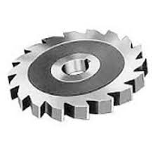
- They have straight or helical teeth.
2. End mills
- End mills are generally HSS cutting tools with three or more flutes.
- They are intended for bulk metal removal with their flutes and unless they are only suitable for side cutting.

- Early end mills and most large end mills have a recessed center at each end of the cutter to facilitate resharpening.
3. Face mill
- A face mill consist of a cutter body that is designed to hold multiple disposable carbide or ceramic tips.
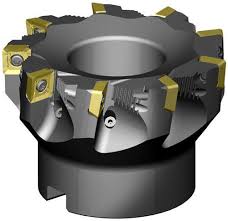
- These tips may be rotates within the holder to present a fresh face to the work piece, this increases the life of the tip and thus their economical cutting life.
4. Slab mill
- Slab mills are using in horizontal or universal milling machines to machine large broad surfaces quickly.

- They have been superseded by the use of carbide tipped face mills that are then used in vertical mills or machining centers.
5. Hollow mills
- These cutters are use in the screw machines.

- In the hollow mills, the cutting teethes are available inside of the surfaces.
6. Metal slitting saws
- A metal slitting saw is similar to a circular saw blade.
- It is mostly use for deep slotting and sinking in cuts.
7. Side and face cutter
- The side and face cutter having cutting teeth on its side as well as its circumference.
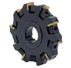
- The teeth on the side allow the cutter to make unbalanced cuts without deflecting the cutter as would happen with a slitting saw or slot cutter.
8. Cylindrical side and face slotting, screw slotting
- Slot drills are generally two fluted cutters that are designed to cut on their end as well as the flutes.
- For this kind of cutters, slot drills, one of their frontal cutting edges should be across the center for drilling function.
9. Single, double and equal angle cutters
- Single angle cutters ( Double and equal angle cutters ) are those which have teeth on the conical or angular face of the cutter and having large flat side.
- Double or equal angle cutter have V -shaped teeth with both conical surfaces at an angle to their end faces.
- They are commonly use for cutting various kinds of metals.
10. T -slot, dovetail, convex, single and double corner rounding cutters
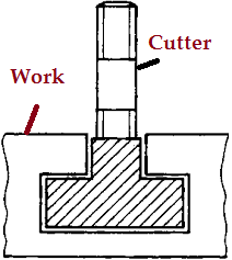
- A dovetail cutter form leaves behind a dovetail slot.
🤗🤗👍👍👍
Good
Thanks….