Table of Contents
Centrifugal Pump
- A centrifugal pump is a type of pump that uses a rotating impeller to move fluids by creating centrifugal force.
- This force pushes the fluid outward and generates a pressure that allows the fluid to be transported through the pump and out into a discharge pipe.
- These pumps are widely used in various industrial purpose like water supply, waste water treatment, and chemical processing etc.
- It is designed to move fluid from a lower level to a higher level.
- This was invented by Denis Papin in the 17th century, a French inventor.
- It is a radial outward flow machine. And it’s commonly used to move liquids through a piping system.
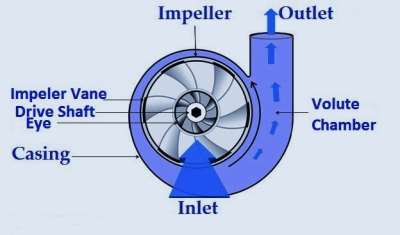
Image: Centrifugal Pump
- It acts as a reverse of an inward radial flow reaction turbine.
- It converts mechanical energy from a motor to energy of moving fluid. Then some of the energy goes into kinetic energy of fluid motion and some into potential energy.
- It’s represent a fluid pressure or by lifting the fluid against gravity to a higher level.
Definition of Centrifugal Pump
- Centrifugal Pump is hydraulic machine which converts the mechanical energy into pressure energy by means of centrifugal force acting on the fluid.
Also Read :
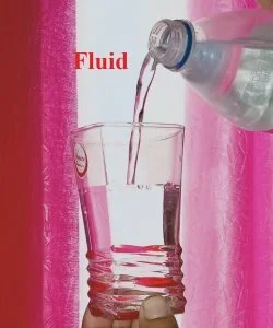
Fluid, Definition, Properties, etc.
Cochran Boiler, Definition, etc.
Working Principle of Centrifugal pump
- A centrifugal pump works on the principle of force vortex flow.
- It means when an external torque is applied to a body of liquid within the pump, it induces a force vortex, leading to an increase in pressure head as the liquid rotates.
ω² r² / 2g
- It means that the rise in pressure head of the rotating liquid is directly proportional to the square of the tangential velocity of the rotating liquid at any point.
- Hence, this elevated pressure, particularly at the impeller outlet, results in the discharge of the liquid at high pressure.
Types of Centrifugal Pump
- The types of centrifugal pump are classified as per following criteria: –
1. Working Head
2. Types of Casing
3. Specific Speed
4. Liquid Handled
5. Disposition of Shaft
6. Number of Impeller Per Shaft
7. Number of Entrance to the Impeller
8. Relative Direction of Flow Through Impeller
1. Working Head
- It is the head at which water is delivered to the pump.
- According to the range of working head, pump may divides into three categories :-
i. Low Lift Centrifugal Pump
ii. Medium Lift Centrifugal Pump
iii. High Lift Centrifugal Pump
i. Low Lift Centrifugal Pumps
- This type of centrifugal pumps mean to work against head upto 15m.
- Impeller is surrounded by a volute casing without providing guide vanes.
ii. Medium Lift Centrifugal Pump
- This uses for head up to 40m and provides with guide vanes.
iii. High Lift Centrifugal Pump
- This is used to delivered water at head 40m.
- These types of centrifugal pumps are generally multistage pumps.
2. Types of Casing
- The casing are of two types and pump is named after the casing it uses.
i. Volute Pump
ii. Turbine Pump or Diffusion Pump
i. Volute Pump
- Volute is of a spiral form and the cross -sectional area of the moving stream gradually increases towards the delivery pipe.
ii. Turbine Pump or Diffusion Pump
- In this types, impeller is surrounded by a guide wheel consists of a number of stationary vanes or diffuser with cross -section gradually enlarging towards periphery.
- Generally, this arrangement employs in multistage pumps.
- Water emerging from the impeller flows past the guide vanes and as the cross -section across flow increases, velocity falls and pressure is built up.
3. Specific Speed
- It is defined as the speed of a geometrically similar pump which would deliver one cubic meter of liquid per second against a head of one meter.
- It is denoted by Ns.
- Specific speed of pump may be given as,
Ns = ( N √Q / H¾ )
Q = Discharge ( m³ )
H = Delivery Head ( m )
4. Liquid Handled
- Depending on the type and viscosity of liquid to be pumped, the pump may be closed or open impeller.
5. Disposition of Shaft
- The shaft may be disposes horizontally or vertically.
- Generally, centrifugal pumps are designed with horizontal shafts.
6. Number of Impeller Per Shaft
- According to this, pumps can be classified as :-
i. Single Stage Centrifugal Pump
ii. Multistage Centrifugal Pump
i. Single Stage Centrifugal Pump
- It has one impeller provided on the shaft.
ii. Multistage Centrifugal Pump
- It has two or more impellers provide on one shaft.
Function of Multistage Centrifugal Pump
- To produce a high head.
- To discharge a large quantity of liquid.
Advantages of Multistage Pumps
- Less loss due to friction.
- Small slip leakage.
- Reduced stresses.
- By proper arrangement of impellers, a thrust can eliminates.
Different Between Single Stage and Multistage Centrifugal Pump
| S.NO. | Single Stage | Multistage |
| 1. | More frictional losses. | Less frictional losses. |
| 2. | Larger axial thrust. | Less axial thrust. |
| 3. | More slip leakage. | Less slip leakage. |
| 4. | More stresses. | Less stresses. |
| 5. | Low head. | High head |
7. Number of Entrance to the Impeller
- In this type of pump, there is single entry or double entry of liquid provides on the side of impeller by means of suction pump.
8. Relative Direction of Flow Through Impeller
- According to this, pump can be classified as :-
i. Radial Flow Pump
ii. Mixed Flow Pump
iii. Axial Flow Pump
i. Radial Flow Pump
- For the most part, all divergent siphons are made with outspread stream impellers.
ii. Mixed Flow Pump
- It is the modification of radial flow type and able to handle the large quantity of water.
- Flow through the impeller is combination of radial and mixed flow.
iii. Axial Flow Pump
- This type of pump is merely calls as centrifugal pump because centrifugal force is not use for generation of pressure.
Parts of a Centrifugal Pump
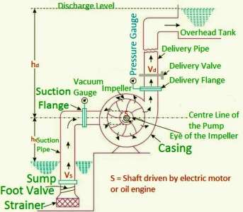
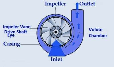
Image: Main Parts Of Centrifugal Pump
- The main parts of a centrifugal pumps are:
1. Impeller
2. Casing
a. Volute casing
b. Vortex casing
c. Casing with guide blades
3. Suction pipe
4. Delivery pipe
1. Impeller
- It is a type of wheel with a series of backward curved vanes.
- This is the main unit of pump which rotates the liquid by externally provided torque by motor.
- On the impeller curve vanes are attached. The shape of vane or blade may be of following three types:
a. Backward vane
b. Forward vane
c. Radial vane
2. Casing
- It is an air tight chamber that is surrounding the pump impeller.
- This is similar to the casing of a reaction turbine. On the basis of casing, shape. They may be following three types:
a. Volute casing
- It is of spiral type in which cross -sectional area increases gradually as well as it surrounds the impeller.
- The main functions of volute casing are:
i. To gather water from the impeller and to transmit it to the conveyance pipe at a steady speed.
ii. To increase the efficiency of the pump by eliminating the loss of head due to change of velocity.
b. Vortex casing
- In vortex casing, a circular chamber is provided between the casing and impeller.
c. Casing with guide blades
- Guide blades are provided along the impeller peripheral hence called guide vanes.
- The area of guide vane increases, thus reducing the velocity of flow through guide vane and correspondingly increasing the pressure of water.
3. Suction pipe
- A pipe whose one end connects to the inlet of the pump and other end dipped into the water in a sump calls as Suction pipe.
4. Delivery pipe
- A pipe, whose one end attach to the outlet of the pump calls as delivery pipe.
- Its other end delivers the water at required height.
Types of Head of a Centrifugal Pump
- The Head of Centrifugal Pump may be expressed in the following ways :-
1. Suction Head
2. Delivery Head
3. Static Head
4. Manometric Head
1. Suction Head
- It is the vertical height of the centre line of the centrifugal pumps above the water surface in the pump from which water is to be lifted.
- It denotes by hs.
2. Delivery Head
- It is the vertical height between the centre line of the pump and the water surface in the tank to which water is delivered.
- It denotes by hd.
3. Static Head
- The aggregate of suction head and conveyance head calls as static head.
- It representes by Hs.
Hs = hs + hd
4. Manometric Head
- It is defined as the head against which a centrifugal pumps has to work.
- It denotes by Hmano.
Losses Occur in Centrifugal Pump
- There are various losses which occur in centrifugal pump are as follows :-
1. Hydraulic Losses
2. Mechanical Losses
3. Leakage Losses
1. Hydraulic Losses
- Water driven misfortunes are the misfortunes happened by the liquid streaming in the siphon.
- These losses are further classified into :-
i. Circular Flow Loss
ii. Fluid Friction Loss
iii. Shock Loss or Eddy Losses
i. Circular Flow Loss
- Due to the flow taker place between two adjacent vanes, relative high pressure is formed along leading edge of vane indicates ( + ) in the travelling edge of blade relatively low pressure forms ( – ).
ii. Fluid Friction Loss
- This loss depends on the area in contact with the fluid flow the roughness magnitude of the surface.
- The loss can considers to vary as the square of the velocity.
iii. Shock Loss or Eddy Losses
- This loss occurs due to improper entry angle of the flow with respect to the blade angle.
- At configuration conditions this misfortune is essentially zero and increments at diminished or expanded stream from typical qualities.
- Shock Loss occurs during two conditions :-
a. Reduction from normal discharge.
b. Increase from normal discharge.
2. Mechanical Losses
- Mechanical losses are losses because of circle rubbing among impeller and fluid which occupies the leeway spaces among impeller and packaging.
- These are likewise the misfortunes because of mechanical erosion in course, pressing organs.
3. Leakage Losses
- Leakage loss in push balance gadgets, organ fixing and clearances between cut water and packaging and bearing seals.
Operational Difficulties in Centrifugal Pump
- The operational difficulties are as follows :-
- Pump fails to start pumping.
- It is not working upto capacity and pressure.
- Pump stops working.
- Pump has very low efficiency.
Cavitation in Centrifugal Pump
- Cavitation starts to show up in divergent siphons when the weight at the suction falls underneath the fume weight of the fluid.
- The force of cavitation increments with the decline in estimation of NPSH.
- In Centrigugal Pump, the pressur is lowest at the inlet of the impeller and hence vapour bubbles form in the suction region.
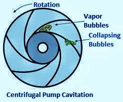
- These air pockets are conveyed alongside the streaming fluid to higher weight district close to the exit of impeller where these fume bubbles breakdown.
- Because of abrupt crumbling of air pockets on metallic surface the high weight is made, which cause pitting activity on metallic surface and creates commotion and vibrations.
- In this way cavities form on the metallic surface.
Definition of Cavitation
- It is characterized as the marvel of development of fume air pockets of a streaming fluid in a locale where the weight of the fluid falls beneath its fume pressure and the unexpected crumbling of these fume rises in a district of higher weight.
Thoma’s Cavitation Factor for Centrifugal Pumps
σ = [ ( Hb ) – ( Hs – hLs ) ] / H
= [ ( Hatm – Hv ) – Hs – hLs ] / H
Where,
Hatm = Atmospheric pressure head in m of water or absolute pressure head at the liquid surface in pump.
Hv = Vapor pressure head in m of water.
and
Hs = Suction pressure head in m of water.
HLs = Head lost because of grating in suction pipe.
and
H = Head developed by the pump.
Effects of Cavitation
- The metallic surfaces are damaged and cavities are formed on the surfaces.
- Due to sudden collapsing of vapour bubbles, considerable noise and vibrations are produced.
- The efficiency of pump decreases due to cavitation.
- Due to pitting action the surface of the pump blades becomes rough and the force exerted on water by the pump blades decreases.
Factors responsible for cavitation
- High impeller speed.
- Little width of suction funnel and gulf of impeller.
- Too high specific speed.
- Required NPSH > Available NPSH.
- High temperature of flowing fluid.
Precautions
- Pressure of flowing liquid in any part of the pump should not allow to fall below its vapour pressure.
- Cavitation resistant material should be used.
Priming in Centrifugal Pump
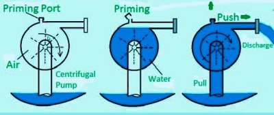
Image: Priming
- It is an operation in which suction pipe, casing of the pump and a portion of delivery pipe is completely filled with water by an outside source before starting the pump.
- This is very essential step in start up of a centrifugal pump. Facts is that centrifugal pump are not capable of pumping air or vapours.
- In priming, centrifugal pump will get fully sub merged in liquid without any air trap inside. This is particularly required when there is a first beginning up.
Necessary of Priming
- The preparing of positive relocation siphons require uniquely at the hour of first beginning.
- For this situation preparing implies filling fluid in packaging and expect to lessen the freedom volume.
- It tends to be expelled the air by their own siphoning activity. This calls Self Priming.
- Priming is not require in reciprocating pumps. But a centrifugal pump is not self priming, Hence priming is necessary.
In other words
- The density of air is low, so head generated by pump is also low even negligible and hence water not be sucked by the pump.
- To avoid this difficulty priming of centrifugal pump is necessary.
Method of Priming
- The pumps can be primed by any of the following methods :-
1. Manually
2. With jet pump
3. With seperator
4. With vacuum pump
1. Manually
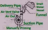
- In this strategy, water is poured in the siphon through channel.
- When preparing is being done, an air escapes through air vent valve.
2. With jet pump

Image: With jet pump
- In this technique, water accessible at high head permits to move through a spout.
- The spout is intended to the point that at the fly outside the spout the weight is not exactly the atm pressure so it is conceivable to suck water from the sump.
3. With seperator
- In this strategy, air seperator is given on the conveyance side of siphon and bowed suction pipe divide is given at the gulf of the siphon.
- Bent suction pipe portion always contain some liquid.
- The fluid heavier than air, so it falls once again into seperator and air moves upward way.
- Accordingly the fluid and air are seperated in seperator.
4. With vacuum pump

Image: With vacuum pump
- In this strategy, the little size responding siphon is utilized preparing radial siphon.
- The suction line of responding siphon associates with the conveyance line of principle radiating siphon.
Different Between Centrifugal Pump & Reciprocating Pump
| S. NO. | Centrifugal Pump | Reciprocating Pump |
| 1. | It gives large discharge and less head. | It gives high head and small discharge. |
| 2. | Priming needs. | It is self primed. |
| 3. | It is simple in construction. | Complicated construction. |
| 4. | Maintenance cost is low. | Maintenance cost is high. |
| 5. | Flywheel is not used. | Flywheel is used. |
| 6. | Installation cost is high. | High installation cost. |
| 7. | Efficiency is high. | Low efficiency. |
| 8. | Starting torque is more. | Low starting torque. |
| 9. | Handle highly viscous fluid. | It can handle low viscous fluid. |
| 10. | It needs no air vessel. | Air vessel uses. |
Advantages of Centrifugal Pump
- Centrifugal pump having a simple and compact design.
- It has a low maintenance cost.
- It provides smooth and non- pulsating flow.
- It is ideal for applications like water distribution and irrigation.
- It is easily available in various shapes and sizes.
- They are particularly well suited for pumping fluids with low viscosity, such as water and thin liquids.
- They are valid to be reliable and durable in difficult situations and have been running continuously.
- It has high efficiency and creates less noise.
Disadvantages of Centrifugal Pump
- Produce cavitation.
- Poor suction power.
- Corrosion.
- Can’t deals with viscous fluids like mud and waste.
- Can’t be able to work high speed.
Applications of Centrifugal Pump
- Almost 70 – 80 % Centrifugal Pumps are using in industry or for domestic purpose.
- Its also using in the field of Food, Chemical, Petrochemical Industries.
- In the field of irrigation and water supply.
- Mining etc.
Conclusion
- Centrifugal Pumps mostly use for commercial purpose and have simple shape so ultimately its cost effective.
- There working mechanism is simple.
- They have less power consumption.
- It can be use to pump suspended or toxic fluids.
- They may not use for volatile or viscous fluids.
For Better Understanding Watch This Video
https://www.youtube.com/watch?v=BaEHVpKc-1Q
Keep it continue sir 👍